Wednesday, March 22, 2017

Power Electronics - MOSFET

Metal Oxide Semiconductor Field Effect Transistor (MOSFET) is a type of transistor used to switch electronic signals. It has four terminals namely; source (S), Drain (D), Gate (G) and Body (B).The MOSFET’s body is normally connected to the terminal of the source(S), which results in three-terminal device similar to other field effect transistors (FET). Since these two main terminals are usually interconnected via short circuit, only three terminals are visible in electrical diagrams.
It is the most common device in circuits that are both digital and analogue. Compared to the regular transistor, a MOSFET needs low current (less than one mill-ampere) to switch ON. At the same time, it delivers a high current load of more than 50 Amperes.

Operation of a MOSFET

MOSFET has a thin layer of silicon dioxide, which acts as the plate of a capacitor. The isolation of the controlling gate raises the resistance of the MOSFET to extremely high levels (almost infinite).
The gate terminal is barred from the primary current pathway; thus, no current leaks into the gate.
MOSFETs exist in two main forms −
  • Depletion state − This requires the gate-source voltage (VGB) to switch the component OFF. When the gate is at zero (VGB) the device is usually ON, therefore, it functions as a load resistor for given logic circuits. For loading devices with N-type depletion, 3V is the threshold voltage where the device is switched OFF by switching the gate at negative 3V.
  • Enhancement state − The gate-source voltage (VGB) is required in this state to switch the component ON. When the gate is at zero (VGB) the device is usually OFF and can be switched ON by ensuring the gate voltage is higher than the source voltage.

Symbol and Basic Construction
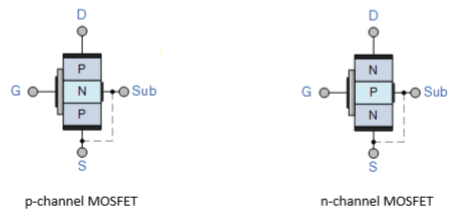
Symbol and Basic Construction
Where, D − Drain; G − Gate; S − Source; and Sub − Substrate
Power Electronics - IGBT

The insulated gate bipolar transistor (IGBT) is a semiconductor device with three terminals and is used mainly as an electronic switch. It is characterized by fast switching and high efficiency, which makes it a necessary component in modern appliances such as lamp ballasts, electric cars and variable frequency drives (VFDs).
Its ability to turn on and off, rapidly, makes it applicable in amplifiers to process complex wave-patterns with pulse width modulation. IGBT combines the characteristics of MOSFETs and BJTs to attain high current and low saturation voltage capacity respectively. It integrates an isolated gate using FET (Field effect transistor) to obtain a control input.

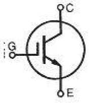
IGBT Symbol

IGBT Symbol
The amplification of an IGBT is computed by the ratio of its output signal to its input signal. In conventional BJTs, the degree of gain (β) is equal to the ratio of its output current to the input current.
IGBT has a very low value of ON state resistance (RON) than a MOSFET. This implies that the voltage drop (I2R) across the bipolar for a particular switching operation is very low. The forward blocking action of the IGBT is similar to that of a MOSFET.
When an IGBT is used as controlled switch in a static state, its current and voltage ratings equal to that of BJT. On the contrary, the isolated gate in IGBT makes it easier to drive BJT charges and hence less power is required.
IGBT is switched ON or OFF based on whether its gate terminal has been activated or deactivated. A constant positive potential difference across the gate and the emitter maintains the IGBT in the ON state. When the input signal is removed, the IGBT is turned OFF.

IGBT Principle of Operation

IGBT requires only a small voltage to maintain conduction in the device unlike in BJT. The IGBT is a unidirectional device, that is, it can only switch ON in the forward direction. This means current flows from the collector to the emitter unlike in MOSFETs, which are bi-directional.

Applications of IGBT

The IGBT is used in medium to ultra-high power applications, for example traction motor. In large IGBT, it is possible to handle high current in the range of hundred amperes and blocking voltages of up to 6kv.
IGBTs are also used in power electronic devices such as converters, inverters and other appliances where the need for solid state switching is necessary. Bipolars are available with high current and voltage. However, their switching speeds are low. On the contrary, MOSFETs have high switching speeds although they are expensive.

Power Electronics - Switching Devices

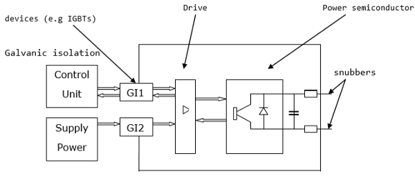
A power electronic switching device is a combination of active switchable power semiconductor drivers that have been integrated into one. The main characteristics of the switch are determined by internal correlation of functions and interactions of its integrated system. The figure below shows how a power electronic switch system works.
switch system
The external circuit of the above diagram is usually held at a high potential relative to the control unit. Inductive transmitters are used to support the required potential difference between the two interfaces.
Features of switch selection :
  • Fast
  • Low power gate
  • High breakdown voltage
  • Low loss during off
  • Cheap

Power Electronics - Introduction

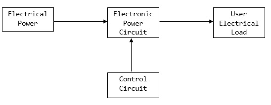
Power Electronics refers to the process of controlling the flow of current and voltage and converting it to a form that is suitable for user loads. The most desirable power electronic system is one efficiency and reliability is close to 100%. Basic block diagram is as below.

Block Diagram

A power electronic system converts electrical energy from one form to another and ensures the following is achieved −
    • Maximum efficiency
    • Maximum reliability
    • Maximum availability
    • Minimum cost
    • Least weight
    • Small size